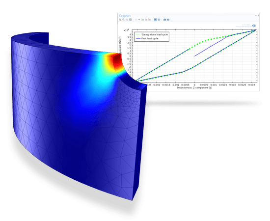
Image made using the COMSOL Multiphysics® software and is provided courtesy of COMSOL.
Low-cycle fatigue resulting from plastic deformation near a hole showing the logarithm of lifetime in terms of number of cycles together with a stress-strain curve for the first few load cycles.
When structures are subjected to repeated loading and unloading due to material fatigue, they can fail at loads below the static limit. A virtual fatigue analysis can be performed in the COMSOL Multiphysics environment with the Fatigue Module, an add-on to the Structural Mechanics Module, which contains a collection of fatigue models. The applicability of each model depends on factors such as material and loading type.
The classical stress- and strain-life methods relate a stress or strain amplitude to a fatigue lifetime. Together with the stress-based and the strain-based critical plane methods, you can evaluate the high-cycle and low-cycle fatigue regime. In applications involving nonlinear materials, you can use energy-based methods or Coffin-Manson type models to simulate thermal fatigue. When dealing with variable loads, the accumulated damage can be calculated from the load history and the fatigue limit.
The fatigue load cycle can be simulated in solid bodies, plates, shells, multibodies, applications involving thermal stress and deformation, and even on piezoelectric devices. In order to improve computational efficiency when dealing with subsurface or surface initiated fatigue, a fatigue evaluation can be performed on domains, boundaries, lines, and in points.
A standing contact fatigue test is a procedure used for testing crack growth on the subsurface level. In such a test, a spherical object is pressed against the tested materials and cycled between a high and low compressive load. No translational movement between the two occurs.
After a period of time, surface cracks can be observed on the flat object’s surface, while further analysis of the component reveals multiple cracks that are present on the subsurface level. The surface is originally hardened, which changes the material properties of the surface in comparison to the material properties of the rest of the object. This surface hardening procedure affects the material strength, hardening, and fatigue properties of the object, while residual stresses are also introduced throughout the depth of the object.
Three distinct layers of fatigue-affected material can be observed. Closest to the surface, the specimen has a strong case layer, while in the core, the material has unaffected material properties. In between these layers, there is a transition layer where both the material properties and the residual stress have strong gradients. All of these effects are incorporated in the simulation of the load cycle.
In this example, fatigue is simulated using the Dang-Van model. The results show stresses that are a combination of the residual state from the hardening process and the structural response to the plastic deformation arising from the indentation of the spherical object. Plasticity occurs only during the first load cycle, while subsequent load cycles are elastic in nature. The second load cycle can therefore be seen as a stable load cycle and is used in the subsequent fatigue study.
A benchmark model of the Rainflow counting algorithm compares results between ASTM and COMSOL fatigue module using a flat tensile test specimen. An extension is made for the cumulative damage calculation following the Palmgren-Miner model and results are compared with analytical expressions.
A fatigue analysis is performed on a wheel rim. The Findley fatigue criterion is examined. The submodeling technique is utilized performed a detailed study on the critical part of a spike. At first a study of the full model is made. The critical part is identified and a submodel is reanalyzed. The road load, which rotates around the wheel, is mapped from the analysis of the full model to the analysis of the submodel.
This example shows how to perform a High Cycle Fatigue (HCF) analysis with a non-proportional load history caused by a transversal force and a torque which are applied in different combinations. Three different fatigue models (Findley, Matake, and Dang Van) are compared.
When a linear guide is loaded above the manufacturer’s specification limit, one concern is whether the contact loads will introduce fatigue spalling. In this system analysis, the entire guide has been analyzed and the mostly damaging contact load has been identified to occur on a rail raceway. Since spalling is initiated by a fatigue crack on the subsurface level, a fatigue evaluation based on the Dang-Van model is performed.
The fatigue evaluation of a moving contact load on a curved surface requires a controlled mesh. The elements’ sizes must be small enough to correctly resolve the contact pressure on the surface. And, as we are analyzing a rolling contact, the contact pressure is dynamic along the surface so that the entire area of the traveling contact must consist of small elements. Moreover, the largest shear stresses in a contact analysis are found on the subsurface level, so that a fine mesh is also required throughout the depth of the model.
A technique for handling such a challenge is demonstrated in this model.
In a cooling system, a microelectronic component has been identified as the critical link. Since the power is repeatedly switched on and off, the component is subjected to thermal cycling. As a results a crack grows through a solder joint and disconnects the chip from the printed circuit board so that the component loses its operational functionality. The lifetime of the solder joints in two ball grid assemblies is predicted based on the Darveaux energy-based model. The fatigue model evaluates damage based on an averaged energy dissipation density in a thin layer where a crack will grow.
This example is based on a model from the Nonlinear Structural Materials Module, Viscoplastic Creep in Solder Joints. Since the model contains several solder joints that are modeled with a viscoplastic material, many degrees of freedom are required in order to simulate the correct creep behavior in all elements. From the fatigue point of view, only the critical part of the model is of interest. In order to capture it, the concept of submodeling is used. This technique requires two steps. In the first one, the full model is analyzed with a coarse mesh in order to simulate the general trends and to identify the critical solder ball. In the second step a submodel with a fine mesh containing the critical part is made and the study is recomputed. The global effects from the full model are transferred to the submodel via appropriate boundary conditions.
A benchmark model for the fatigue module. A cylindrical test is subjected to non-proportional loading. Three stress based models: Findley, Matake, Normal stress, are compared to analytical values and to each other. The non-smooth behavior of the Matake model is captured and discussed.
Analyzing fatigue with simulation, rather than running fatigue experiments, is a much quicker way to determine whether a certain design will fail after repeated loading and unloading. This application allows you to evaluate the fatigue life of a frame with a cutout. It is useful for understanding the concept of fatigue and how to build an equivalent app for your own designs.
The Frame Fatigue Life app allows you to modify the cutout geometry and test different load types and materials. Load histories and S-N curves can be read from text files.
As the geometry has been parameterized, the app can be used to determine geometric parameter sensitivities and obtain an optimal configuration.
A frame with a central cutout is subjected to a random load consisting of 1000 load events. The external load, recorded using three strain gauges, is simulated using superposition of three unit loads. The stress state around the cutout is obtained with the Rainflow cycle counting algorithm. The damage is estimated using the Palmgren-Miner linear damage rule.
A load carrying component of a structure is subjected to multi-axial cyclic loading during which localized yielding of the material occurs. In this model you perform a low cycle fatigue analysis of the part based on the Smith-Watson-Topper (SWT) model.
Due to localized yielding, you can use two methods to obtain the stress and strain distributions for the fatigue evaluation. The first method is an elastoplastic analysis with linear kinematic hardening, while the second is a linear elastic analysis with Neuber correction for plasticity, based on the Ramberg-Osgood material model. This example explores the second method. In the model “Low-Cycle Fatigue Analysis of Cylinder with a Hole”, the same problem is solved using the full elastoplastic approach.