LiveLink™ for PTC® Pro/ENGINEER®
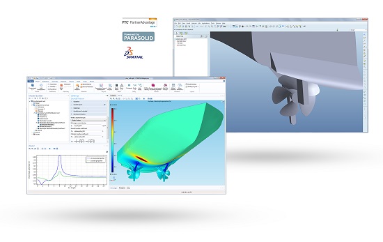
Image made using the COMSOL Multiphysics® software and is provided courtesy of COMSOL.
CORROSION MITIGATION: Simulation of impressed current cathodic protection on a ship hull. Results show electrolyte potential for a ship hull with a coated propeller.
LiveLink™ for PTC® Pro/ENGINEER®
LiveLink™ for PTC® Pro/ENGINEER® provides the capability to integrate 3D CAD design with multiphysics simulation to update your workflow and boost productivity. PTC® Pro/ENGINEER® is a versatile CAD solution that enables engineers to create parametric solid models of their product designs. In combination with COMSOL Multiphysics®, you have the ability to create your design in Pro/ENGINEER and then simulate your design in the COMSOL environment.
Creating a COMSOL model geometry from your CAD design is straightforward and allows you to evaluate the performance of your product design in the intended operating environment. Essentially any relevant physical effects and their interactions can be included in a COMSOL model to produce accurate simulations of your design. LiveLink™ for PTC® Pro/ENGINEER® includes features for CAD geometry repair, bidirectional model updates, and direct CAD parameter access from within the COMSOL environment to facilitate the integration of multiphysics simulation into your design process.
Importing your 3D CAD file is another way to create a COMSOL model geometry from your design. The file import functionality included with LiveLink™ for PTC® Pro/ENGINEER® is derived from the CAD Import Module and supports the import of the widely used ACIS®, Parasolid®, STEP, and IGES formats in addition to the SOLIDWORKS®, Inventor®, PTC® Pro/ENGINEER®, and PTC® Creo® Parametric™ formats. Optional support for the CATIA® V5 file format is also available. By default, the imported CAD design is represented as a Parasolid geometry in COMSOL Multiphysics that can be further modified or updated. For example, you can combine imported geometry with geometry drawn in the COMSOL environment, and you have several possibilities for partitioning the geometry objects to create additional computational domains. This can be useful if you want to extend the simulation to the regions surrounding the imported solid objects of a CAD design. File export from COMSOL Multiphysics in the ACIS and Parasolid formats allows you to share your geometry and exchange data with other CAD programs and viewers.
This model computes the fundamental eigenfrequency and eigenmode for a tuning fork that is synchronized from Pro/ENGINEER via the LiveLink interface. The length of the fork is then optimized so that the tuning fork sounds the note A, 440 Hz.