Image made using the COMSOL Multiphysics® software and is provided courtesy of COMSOL.
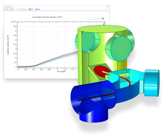
In an ion implanter, the average number density of outgassing molecules along the beam path is used as a figure of merit to evaluate the design. It must be computed as a function of wafer angle, with rotation about one axis.
Vacuum engineers and scientists use the Molecular Flow Module to design vacuum systems and to understand and predict low-pressure gas flows. The use of simulation tools in the design cycle has become more widespread as these tools improve understanding, reduce prototyping costs, and speed up development. Vacuum systems are usually expensive to prototype. Therefore, an increased use of simulation in the design process can result in substantial cost savings. The gas flows that occur inside vacuum systems are described by different physics than conventional fluid flow problems. At low pressures, the mean free path of the gas molecules becomes comparable to the size of the system and gas rarefaction becomes important. Flow regimes are categorized quantitatively via the Knudsen number (Kn), which represents the ratio of the molecular mean free path to the flow geometry size for gases:
| Flow type | Knudsen Number |
|---|---|
| Continuum flow | Kn<0.01 |
| Slip flow | 0.01<Kn<0.1 |
| Transitional flow | 0.1<Kn<10 |
| Free molecular flow | Kn>10 |
Differentially pumped vacuum systems use a small orifice or tube to connect two parts of a vacuum system that are at very different pressures. Such systems are necessary when processes run at higher pressures and are monitored by detectors that require UHV for operation. In this model, gas flow through a narrow tube and into a high vacuum chamber is approximated using an analytic expression for the flow rate. The model can also be adapted to use experimental data directly. The results obtained by coupling the analytic model to the free molecular flow interface are compared with a simulation that incorporates free molecular flow in both the tube and the UHV part of the system.
The Ion Implanter Evaluator app considers the design of an ion implantation system. Ion implantation is used extensively in the semiconductor industry to implant dopants into wafers.
Within an ion implanter, ions generated within an ion source are accelerated by an electric field to achieve the desired implant energy. Ions of the correct charge state are selected by means of a separation magnet, which bends the ion beam to ensure that ions of a particular charge-to-mass ratio are the only ones that reach the wafer. The energy dose and angle of the ion beam are both key parameters for the process.
The app allows the user to change the angle of the wafer as well as the molecular weight of the outgassing species, the outgassing rate, and the surface temperature. The cryo and turbo pump speeds can also be adjusted.
The number density, pressure, molecular flux, as well as the average number density along the beam line can be visualized.
This benchmark model computes the pressure in a system of outgassing pipes with a high aspect ratio. The results are compared with a 1D simulation and a Monte-Carlo simulation of the same system from the literature.
This model computes the transmission probability through an RF coupler using both the angular coefficient method available in the Free Molecular Flow interface and a Monte Carlo method using the Mathematical Particle Tracing interface. The computed transmission probability determined by the two methods is in excellent agreement with less than a 1% difference. This model requires the Particle Tracing Module.
This model computes the particle flux, number density and pressure on the surface of a plate that rotates in a highly directional molecular flow. The results obtained are compared with those from other, approximate, techniques for computing molecular flows.
Computing molecular flows in arbitrary geometries produces complex integral equations that are very difficult to compute analytically. Analytic solutions are, therefore, only available for simple geometries. One of the earliest problems solved was that of gas flow through tubes of arbitrary length, which was first treated correctly by Clausing. Later, the integral expressions he derived were computed more accurately by Cole. These authors derived values for the transmission probability of molecules incident on a tube of arbitrary length, which is independent of the pressure, provided that the Knudsen number is much greater than one (in the molecular flow regime).
This model uses the Free Molecular Flow interface to compute the transmission probability for the molecular flow of molecules through a microcapillary with different length / radius ratios. The results are compared with the accurate solution as computed by Cole.
This model shows how to simulate the time-dependent adsorption and desorption of water in a vacuum system at low pressures. The water is introduced into the system when a gate valve to a load lock is opened and the subsequent migration and pumping of the water is modeled.
A charge exchange cell consists of a region of gas at an elevated pressure within a vacuum chamber. When an ion beam interacts with the higher-density gas, the ions undergo charge exchange reactions with the gas, creating energetic neutral particles. It is likely that only a fraction of the beam ions will undergo charge exchange reactions. Therefore, in order to neutralize the beam, a pair of charged deflecting plates are positioned outside the cell. In this way, an energetic neutral source can be produced.
The Charge Exchange Cell Simulator app simulates the interaction of a proton beam with a charge exchange cell containing neutral argon. User inputs include several geometric parameters for the gas cell and vacuum chamber, beam properties, and the properties of the charged plates that are used to deflect the remaining ions.
The simulation app computes the efficiency of the charge exchange cell, measured as the fraction of ions that are neutralized, and records statistics about the different types of collisions that occur.