Image made using the COMSOL Multiphysics® software.
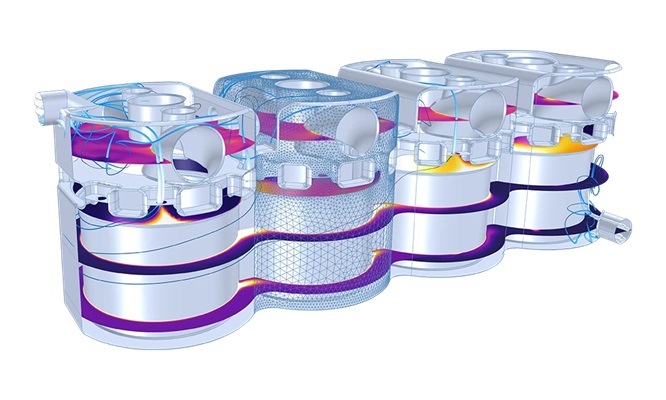
Temperature and Flow Field of engine gasket holes.
The Liquid & Gas Properties Module provides tailor-made functionality for specifying properties of liquids and gases used in the modeling of fluid flow, energy transport, and mass transfer. The fluid properties provided are often dependent on temperature or temperature and pressure as well as on time and space. When modeling mixtures with multiple components, the impact of the chemical composition and changes therein can also be accounted for. The main components provided with module consist of a built-in properties database for chemical species, together with a thermodynamic properties calculator. When used together, these two make it possible to compute thermodynamic properties and transport properties for pure solutions and mixtures of chemical compounds in gas or liquid form. Examples of properties that can be computed are heat capacity, thermal conductivity, density, and diffusivity. Properties can be calculated for fluids consisting of a single gas phase or a single liquid phase and for liquid-liquid, gas-liquid, and gas-liquid-liquid systems. For multiphase systems, the equilibrium composition can also be calculated to, for example, to calculate the phase envelope for a liquid mixture at equilibrium with its gas phase (flash calculations).
This example simulates the underground storage of CO2 in a part of the Johansen formation off the coast of Norway. The CO2 is injected using an injection well at a rate of 15 kg/s over a period of 25 years, after which the well is closed. The model is used to compute the spreading of CO2 over the simulation domain during the injection phase and during the 25 years directly following the shut down of the injection well. This model contains information from the Johansen dataset, which is made available here under the Open Database License (ODbL). Any rights in individual contents of the database are licensed under the Database Contents License: http://opendatacommons.org/licenses/dbcl/1.0/. Data courtesy of the Norwegian Petroleum Directorate (NPD), the University of Bergen (UiB) and SINTEF.
Heat pipes are designed to transfer heat efficiently through vaporization, mass transfer, and condensation of a working fluid. They are found in a wide variety of applications where thermal control is of importance, with cooling of electronics being a prominent example. Inside a heat pipe, the temperature difference between the hot and cold sides together with the temperature dependence of the vapor pressure, induce a pressure difference across the vapor chamber. The pressure difference, in turn, drives the vapor from the hot to the cold side. The vaporization acts as a heat sink at the vapor–wick interface at the hot side, and conversely, the condensation as a heat source, at the cold side. This model demonstrates how the laminar flow in the vapor chamber of the heat pipe can be coupled to the liquid phase transport through the porous wick, and how thermodynamic properties of water can be obtained from the database in the Liquid & Gas Properties module. The importance of vapor transport is compared to the conductive heat transfer in the pipe wall. The former dominates the latter by several orders of magnitude.
The engine block of a car includes a cooling jacket to remove excess heat from combustion. The cooling jacket consists of open spaces in the cylinder block and the cylinder head. When the engine is running, a coolant fluid is pumped through the jacket to keep the engine from overheating. Optimizing the heat removal is important to minimize coolant boiling, prevent engine failure, and, more recently, improve overall efficiency through waste heat recovery. This example demonstrates how the Thermodynamics feature can be used to evaluate the performance of different engine coolants.
Modeling and simulation is useful for evaluating the feasibility of storing hydrogen underground. In this example of a geological formation, hydrogen is injected through an injection well at a rate of 1 kg/s over a period of 2 years, until it is ready to be extracted and discharged through charge–discharge cycles. The model visualizes the hydrogen volume fraction in a dome-shaped aquifer.